BASIC SQUARE GROOVE WELDS for ELECTRON BEAM WELDING
"SQUARE GROOVE" FOR ELECTRON BEAM WELDING
FIGURE 1
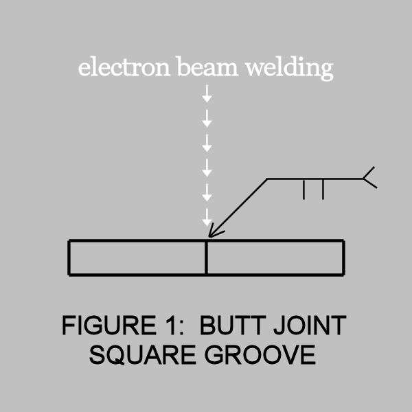
The square groove butt joint, illustrated in Figure 1, may be regarded as a basic joint design for electron beam welding. Generally, it is the most practical and most efficient configuration to use.
This joint design may be used for materials as thin as 0.005" or
as thick as 1" or more.
The use of this design assumes accessibility to both surfaces for machining and inspection purposes.
"INTEGRAL BACKUP" FOR ELECTRON BEAM WELDING
FIGURE 2
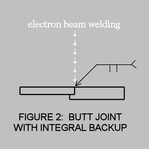
The butt joint configuration illustrated in Figure 2 is sometimes called a butt-lap joint, and is used to provide alignment and filler material.
The alignment feature can simplify tooling requirements, prevent mismatch in linear welds and is useful as a self-centering device in its cylindrical parts.
Although the additional material is located on the root surface, it will provide a positive top bead reinforcement. It can provide material to stop the beam within the thicker member to prevent weld metal spatter associated with full penetration weldments.
It can also be used to an advantage with alloys, such as aluminum, and solving weld root porosity problems.
"MODIFIED INTEGRAL BACKUP" FOR ELECTRON BEAM WELDING
FIGURE 3
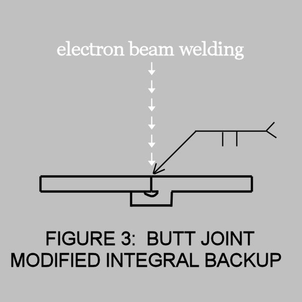
The modification to the integral backup, shown in Figure 3, is sometimes utilized for crack sensitive materials.
This is a relatively expensive joint preparation, but is used in fatigue-critical applications where the notch effect of non-fused material and a change in cross-section is minimized.
"TOP SCAB" FOR ELECTRON BEAM WELDING
FIGURE 4
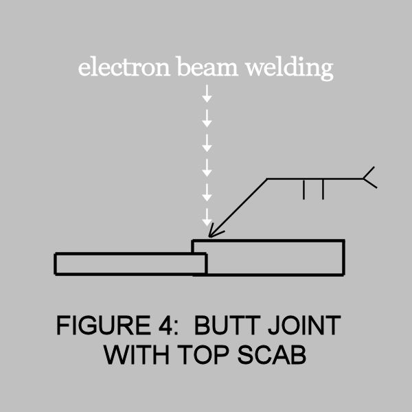
The configuration shown in Figure 4 is useful where the face surface of the weldments is critical
or where undercut or under fill is apt to be a problem.
Titanium and magnesium alloys are materials most commonly requiring this approach to providing adequate filler material.
A scribe line is used for weld joint alignment and weld tracking.
"ANGULAR BEAM" FOR ELECTRON BEAM WELDING
FIGURE 5
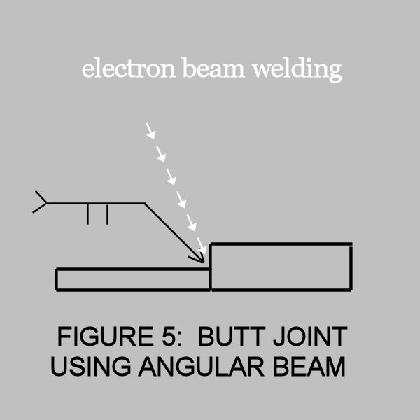
The technique shown in Figure 5 is used where mating parts vary in thickness, scarfing of the thicker member is undesirable and welding from the opposite side is not feasible.
It is essential to widen the beam in order to assure a fusion of both abutting surfaces of the weld joint.
The angle should be only as large as necessary to assure no scarfing, but not so large as to exaggerate the tendency to produce lack of root fusion. This is not usually a problem with joint thicknesses up to 0.375 inches.
Thicker joints may require an angle cut on the joint preparation to prevent the missed joint type, lack of fusion defect


